.......Inspire enables design engineers and product designers to quickly and conveniently perform CAE structural analysis. It also makes it easy to solve engineering problems that involve structure, mechanisms, and optimization in a single environment. Using Altair’s advanced OptiStruct optimization solver, it generates an ideal shape based on the defined design space, material properties, and loading requirements. The software is easy to learn and works together with existing CAD tools to reduce development cost, time, material usage, and product weight right from the earliest stages of structural design.
【 Product Highlights 】
-
Efficient structural concept design and simulation
-
Supports optimization and analysis of parts and assemblies
-
Fast and convenient geometry cleanup
-
Linear analysis and modal analysis
-
Easy to learn and use
-
User-friendly interface
【 Advantages 】
Faster design
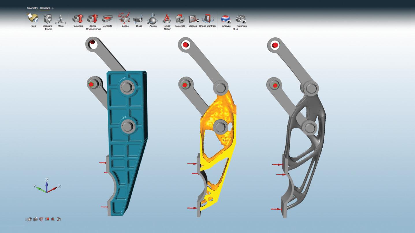
.......Generate structural concepts that meet performance requirements at the start of the design cycle. Compared with the traditional “design–verify–redesign” approach, this process saves a significant amount of time and improves overall workflow efficiency.
Smarter design
.......Inspire makes it easy to explore “what-if” scenarios where the design space, connections, loading conditions, and shape controls can all be modified at any time. The resulting concepts often provide highly valuable design insights.
Lighter designs
.......Inspire uses material efficiently, placing it only where it is needed to meet structural performance requirements. Reducing design weight saves material cost, improves performance, and lowers transportation costs.
【 Features 】
Geometry creation and simplification
Use Inspire’s modeling tools to create, modify, and remove features in solid models:
-
Sketching tools: create and edit parts using lines, rectangles, circles, and arcs, and apply geometric constraints such as mirror, scale, rotate, push/pull, tangency, and perpendicularity.
-
Trim/break: trim and break curves in sketches.
-
Push/pull: extrude planar or cylindrical faces to create solid geometry and modify dimensions.
-
Feature removal: remove embosses, fillets, rounds, holes, and slots; fill holes and slots; and create patches and bridges.
-
Mid-surface extraction: the mid-surface extraction tool allows users to extract mid-surfaces from constant-thickness 3D solids.
Optimization setup
Inspire provides multiple optimization options:
-
Optimization objectives: maximize stiffness or minimize mass.
-
Stress constraints: limit global maximum stress.
-
Displacement constraints: restrict maximum displacement at required locations and in specified directions.
-
Angular velocity and acceleration loads: tools that allow users to define rotational speed and axis for the entire model.
-
G-loads: the G-load tool allows users to simulate acceleration acting on the model.
-
Displacement constraints: displacement constraints can be applied to limit deflection at desired locations and directions.
-
Temperature loads: the temperature tool allows users to simulate the effect of temperature changes in the model.
-
Export to OptiStruct: designers can export input files for OptiStruct to perform advanced simulations.
Connections and assemblies
Optimize and analyze complete parts and assemblies directly in Inspire.
-
The contact tool allows users to search for neighboring parts and specify whether they should be joined, in contact, or not in contact.
-
Using fastener and connector tools, users can add bolts, screws, pins, or sliding pins to connect multiple parts in a model.
Manufacturing constraints and shape controls
With Inspire’s shape control capabilities, generated design concepts are not only structurally efficient but also easier to manufacture.
- Symmetry plane: enforce symmetric shapes with respect to a plane.
- Cyclic symmetry: generate cyclically symmetric shapes.
- Draw direction: single or double draw directions to facilitate casting and stamping.
- Stamping constraint: generate topology with constrained cross-sections along a specified direction.
Solution analysis
Linear static and modal analysis with corresponding post-processing outputs such as displacement, factor of safety, yield, tension and compression percentages, von Mises stress, and maximum principal stress.
Customizable material database
Includes data for commonly used materials such as aluminum, steel, magnesium, and titanium, and also allows users to add custom materials.
PDM
Inspire allows users to open models from Teamcenter or Windchill PDM systems, and also supports saving model files back to these PDM systems from Inspire.
Part associativity
-
Parent-child relationship: if a part is created via copy-paste, when it is updated the corresponding duplicated part will update automatically. This information can also be imported from CAD files.
-
Repeat patterns: when a design space in a model is reused multiple times as separate instances, Inspire automatically applies repeat patterns so that they produce the same shape.
Interactive visualization of results
Use a simple slider to add or remove material and explore the optimized shape. Users can decide which features are important and then choose the concept design that best fits their needs.
Assembly configurations
Create multiple assembly configurations to evaluate different design options and optimization results.
Final model creation
.......Create PolyNURBS:PolyNURBS creation and editing tools let users quickly create freeform solid geometry. The resulting solids are smooth, continuous, and ready for manufacturing.
Multiple language options
.......Chinese, English, French, German, Italian, Japanese, Korean, Portuguese, Spanish.
Shape controls and design constraints
Geometry input
-
ACIS
-
Catia (V4 & V5)
-
Creo
-
IGES
-
Inventor
-
JT
-
Parasolid
-
Pro/E
-
SolidWorks
-
STEP
-
STL
-
UG NX (Unigraphics)
Geometry output
|
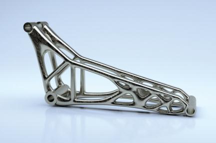
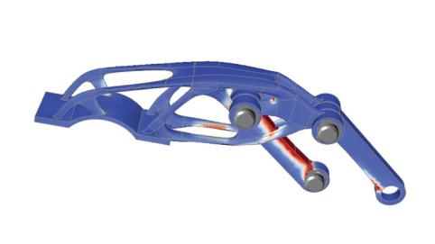
Optimized 3D-printed bicycle rocker arm
|
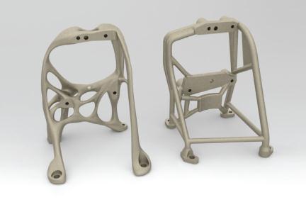
Optimized and 3D-printed metal aerospace bracket
|
Optimized robotic gripper arm
|
Inspire Free Course Resources
Altair Inspire, with its intuitive design environment and high-efficiency optimization capabilities, is widely appreciated by engineers. We now offer “Inspire Free Course Resources,” designed especially for professionals who are unable to attend in-person classes. These courses provide more flexible learning times, allowing you to master the powerful features of Altair Inspire anytime, anywhere.
Click now to start your learning journey.
Start learning◆
Richin Tech is the "expert in CAE and AI data analytics", and we have completed many successful case studies.
▶ Contact us now to get more information.
▶ Subscribe to the Richin YouTube channel to explore more about CAE and data analytics.